PUMP AND MOTOR MOUNT SOLUTION WHEN THE EXISTING PIPES ARE OF A DIFFERENT HEIGHT
- Tom Weaver
- Mar 27, 2019
- 3 min read
Updated: Mar 28, 2019
HOW DO YOU CREATE A PROPER PUMP AND MOTOR MOUNT WHEN THE EXISTING PIPES ARE OF A DIFFERENT HEIGHT?
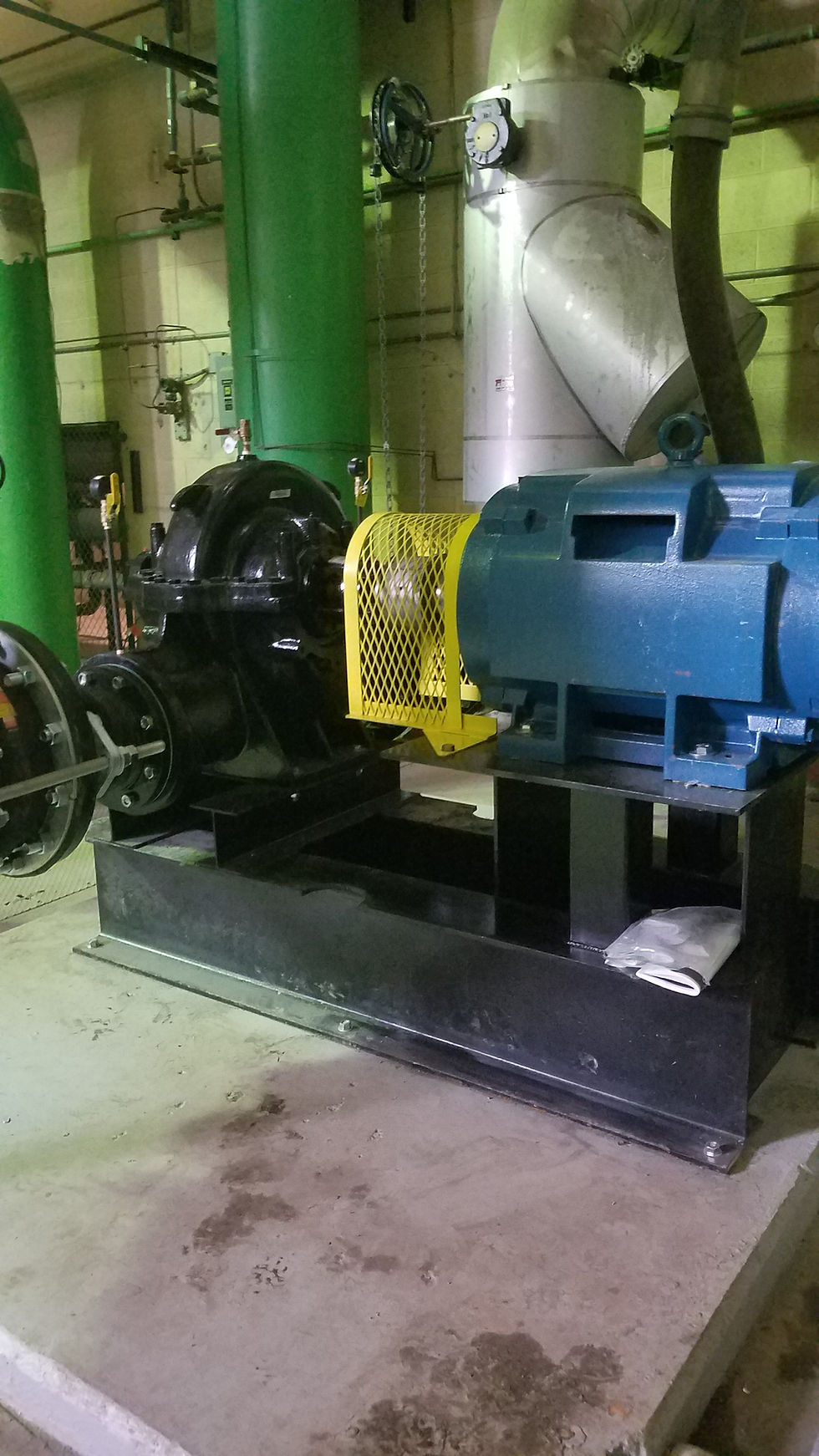
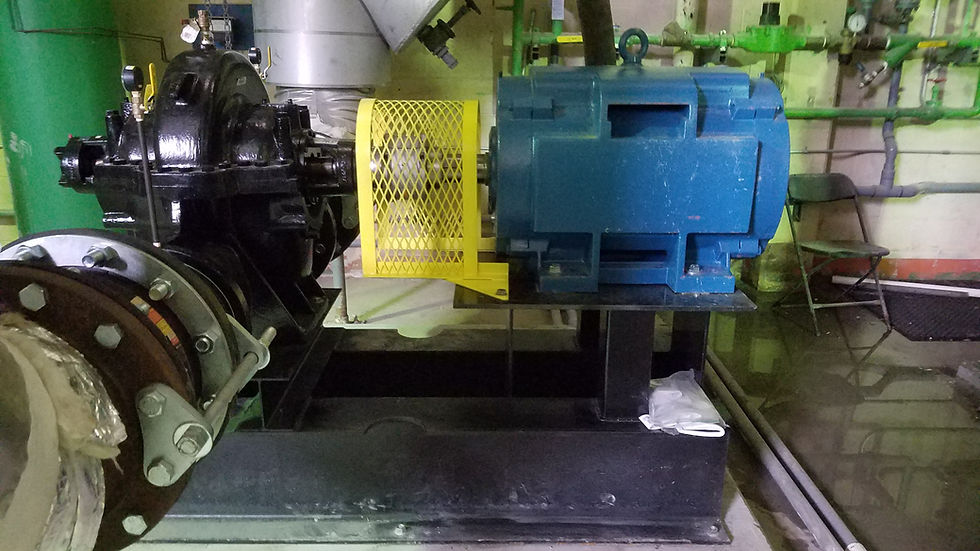
TMW Systems LLC was presented with that problem on a recent project. We were asked to create a pump stand and motor mount for a new pump and motor that was to be installed at an existing facility. The old pump and motor were worn out and the pad was in bad shape. The existing unit was mounted on a floating pad that was supported by spring assemblies to the base, or housekeeping pad.

The project called for the installation of a new pump, motor, coupling and base. The decision to scrap the floating pad was made when it was seen that the floating pad had suffered damage to its infrastructure as well as the spring assemblies. Our recommendation was to eliminate the floating pad entirely and mount the new pump and motor directly onto the housekeeping pad. The fact that the new motor had a drive unit for start-ups and that the new pump was a higher efficiency unit aided in making that decision.
From this point, the normal procedure would be to determine the centerline of the pipe that was to be mated and proceed with the design of the base unit using both engineering drawings from the specification sheets and field measurements. The design was completed and fabrication of the mount commenced.
The problem that we faced was that the centerline of in inlet and outlet were of a different height. For a brand new installation, the pump is located and the piping fitted to the desired location. For replacement systems, the piping is existing and the pump fitted to the piping. However, in this instance, the centerlines of the inlet and outlet piping differed in height by one inch due to settling of the building over time. Altering the existing piping was not an option. This left us faced with a decision as to how to overcome this discrepancy.

The pump must be level in all orientations, solidly anchored and aligned with the motor for optimal performance and to avoid damage to the casing, bearings, and internal workings. All manufacturers cannot stress this fact enough for the durability and sustained life of their equipment. However, the pipe height was still different by one inch. The solution was to create custom eccentric reducers for one or both sides. The face to face dimensions, amount of pitch and welding considerations were taken into account to determine the best course of action. For this project, the suction and discharge of the pump was an 8” – 150# flange face. From this, and 8” – 150# to 14” – 150# eccentric reducer connected to the expansion joint and piping system. The face to face required for the pipe configuration as 12.75” with the height differential of 1”. A standard eccentric reducer of this type has a maximum face to face of 13.75” so we knew that we had room to create a custom piece.
The standard eccentric required cutting and beveling on both ends for the configuration necessary. In addition, the slip-on flanges needed to be opened up on a lathe to accommodate the new angles of the eccentric. We hand beveled our reducer following our cutting. A bevel cutting device would work well, assuming that it travels along the cut surface. A jig could be created for a vertical turret lathe or a horizontal bore could also be employed. However, being only one project, doing the beveling by hand seemed to be the best option. Fitting of the unit called for ensuring that the alignment was correct and that the flanges ended up plumb and parallel while overcoming the height differential. When the correct fitting was complete, the unit was welded out according to procedures and delivered to location. The fit was within tolerance and the entire process did not stall the projected installation completion date.

Should you have an unusual or unique application, call us at (714) 371-8435 or you can always visit us on the internet at https://www.tmwsystemsllc.com. We are always ready to provide you with a free quote, leave us a message on our contact page. We specialize in providing solutions to one of a kind parts.
